CAN bus uses differential twisted pair cabling at the physical layer, which inherently suppresses common mode interference. However, relying solely on differential signaling and twisted pairs can only mitigate interference to a certain extent. In extreme cases, such as lightning strikes, instability may still occur.
To enhance the interference resistance of the CAN bus, methods to improve both common mode and differential mode interference suppression are utilized. Here’s a detailed approach addressing these interferences:
Types of Common Mode Interference:
Inductive Coupling from Strong Electromagnetic Environments: External electromagnetic forces can induce voltages simultaneously across twisted pairs.

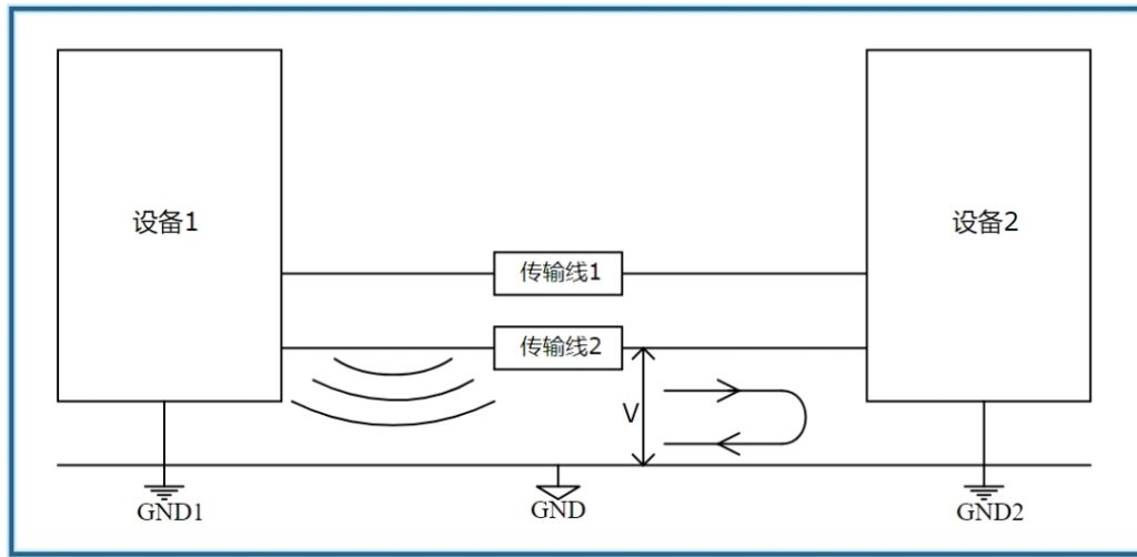
Potential Differences between Communication Devices: Devices at different electrical potentials can introduce errors.

High Potential Differences between Twisted Pairs and Ground: Significant voltage differences relative to earth ground can create interference.
Common Differential Mode Interference: This includes voltage spikes and potential fluctuations within the circuit loop.
Strategies to Mitigate Interference:
1. Shielded CAN Bus Cables:
To counteract the first type of common mode interference, shielded twisted pair cables can be used. The metal shielding layer helps convert most of the electromagnetic energy into heat through induction of eddy currents, rather than allowing it to propagate as voltage along the transmission line.

2. Balancing Potentials:
For the second type of common mode interference, especially when communication devices are far apart, linking the shielding layers of the transmission lines can equalize potentials by providing a low impedance path for current flow, quickly balancing the potential differences.
3. Effective Grounding:
Concerning the third type of common mode interference, it is crucial to ground the shielding of the twisted pair cables effectively at both ends of the device housings. Proper grounding of the device housings ensures that most interference currents are rapidly directed to the ground.
4. Protection Against Differential Mode Interference:
Using protection circuits such as Transient Voltage Suppression (TVS) diodes, bypass filtering capacitors, and gas discharge tubes can help shunt excess voltage spikes to ground, keeping peak interference within safe limits. Additionally, Electrostatic Discharge (ESD) protection devices can prevent static damage. For those working with other types of cables, it’s useful to know how to test coax cable, especially when ensuring signal integrity across different systems.
Enhanced Protection Measures:
1. Electrical Isolation of CAN Interfaces:
To avoid circuit damage from ground loops and limit the extent of interference, it’s advisable to incorporate electrical isolation between the CAN interface and the power supply. Modern approaches often employ isolated transceivers, which offer reduced costs, shorter development times, and higher reliability.
2. Increasing the Twisting of the CAN Bus Wires:
The physical layer of the CAN bus employs differential transmission via CAN_H and CAN_L lines. In environments with substantial interference, increasing the number of twists per meter from the standard 33 to 45-55 can enhance interference resistance. Cable specifications such as core cross-sectional area and the capacitance between wires and shielding also play significant roles.
3. Adding Surge Protectors:
Surge protection circuits are crucial when isolators might be overwhelmed by high interference or surges, enhancing the robustness against high-energy pulses.
4. Fiber Optic Conversion:
In severely disruptive environments, converting CAN signals to fiber optics can significantly enhance interference resistance. Fiber optics are immune to electromagnetic pulses and lightning strikes, providing a robust alternative.
Simple Interference Mitigation Techniques:
Avoiding interference sources is a straightforward and commonly used strategy. In practice, it’s crucial to segregate strong and weak electrical systems as much as possible, maintaining distance to minimize interference. If unavoidable, arranging cables to cross at right angles can also help reduce interference effects.